|

| Print this page - use Landscape |
Search the WeetHet Pages |
|||||||||||||||||||||||||||||||||||||||||||||||||||||||||||||||||||||||||||||||||||||||||||||||||||||||||||||||||||||||||||
| WeetHet is being updated! - Current articles will slowly move to www.tweaking4all.com For excellent webhosting that is reliable and affordable, we highly recommend: LiquidWeb |
||||||||||||||||||||||||||||||||||||||||||||||||||||||||||||||||||||||||||||||||||||||||||||||||||||||||||||||||||||||||||||
|
On this page ...
Page Overview
On all off these pages you will find very valuable tech information on the overclocking subject. Downside is that the information is sometimes incomplete, to hard to do it yourself or simply too technical in general. This overclocking, does not require any modifications on the mainboard your are using! Keep in mind though:
Tip: for revieving your CPU information, use WCPUID, visit the H.Oda homepage for more details. Just to indicate that it really works, some result:
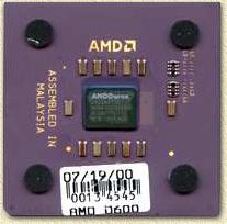
So I bought myself an AMD Duron 600 for about $140 at Korving Computers (Audie: since I mention you here, how about some sponsoring ?). And this what it looks like:
A few things we notice on this CPU. On the right you see a couple of microscopic
bridges called L1, L2, L3 and L4.
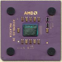
We also notice the white label. After removing this new bridges are revealed, the L5, L6 and L7.
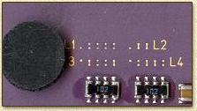
OK, the pictures I made are maybe not to clear on what I'm refering to, so let's some in for a minute. I marked the L1, L2, L3 and L4 area as A. The B area marks the L5, L6 and L7.
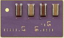
When zooming in to these ares we see the bridges I mentioned (and YES they are very small). Area A - showing L1, L2, L3 and L4 (rotated 90 degrees counter clock wise).
Area B - showing L5, L6 and L7.
!! These bridges are the key to overclocking the Athlon/Duron !! The bridges are used for hardware locking the Duron or an Athlon Socket-A CPU. An unlocked Duron would have all bridges connected and the BIOS of your mainboard would then have to set Voltage, busspeed and multiplier. Since most boards do not support this and since autodetection of the CPU settings is a must the Duron is locked. AMD uses a special type of laser to open the bridges if needed. The names of the bridges and purpose of the bridges are not that important but I'll briefly tell you what we need to do with them.
Let's first create a list of possible settings. Possible settings - Voltage (L7) The voltage settings are often changed when overclocking a CPU. Some mainboards (like the MSI 6330 - K7T Pro) support changing the voltage in the BIOS, other boards don't. To get right to the worse case scenario: let's assume we have a board that doesn't support voltage setting. In the table below I create an overview (thanks to Thomas pabst). The single dot in these pictures are there for orientation only. Also: the images are orientated, matching the previous zoom-in pictures of the CPU.
As you can see, 1.850 Volt is the max we can get and 1.500 Volt is the default voltage used by a Duron. For overclocking to 900 Mhz my computer works at 1.825 Volts. When doing so, make sure you have to quality cooling ! My cooler actially is pretty good and the cooling fan is running at app. 6600 rpm, which is pretty high. Possible settings - Frequency Multiplier (L3, L4 and L6) Next step is to change the multiplier
settings. Bridges L3, L4 and L6 are used to do so.
As you can see, 1200 appears to be the max used by a Duron - don't count on it that you can overclock that far! I (and several others) tried 900+ Mhz, but it appears that 900 Mhz is the maximum you will get from just changing the multiplier. I still have to do some testing by changing the FSB from 100 Mhz to 100+ Mhz. Since the multiplier seems to run at 9, even a silly additional 5 Mhz could push the Duron to the 1 Ghz barrier ! But, like I said, I still have to test this. At this moment when I'm writing this article, with the Duron running a performance test (it has been running for 6 straight hours now, playing DivX movies and the temperature remains a steady 41 degrees celcius at 900 Mhz. The procedure - Step 1: opening bridges I can tell you this: this is the HARD part ! Before we can start experimenting with settings, we must open all bridges (or at least the onces we want to be open). I have to admit that I didn't do it the safe way: I just opened the settings required for 900 Mhz to strat with. The bridges are damn small (you might want to get a magnifying glass right now). A medical scalpel does NOT do the job (it took me several attempts to realise this). Finally I used one of the mini drilling machines (like the one from Dremel - as suggested by James D. Flodin on Tom's Hardware page). Be very very carefull what you are doing
! We do not want the entire contact to be gone ! The procedure - Step 2: closing bridges I did not know right away how to close the bridges with an easy removable solution (one might want to return to the CPU's original setting - in case overclocking did not work well). One solution might be using one of those pen, for fixing PCB's. The pen is capable of drawing electronic conductive lines. Then I remember a neat trick (thanks Dad!): a simple pencil (I used an regular HB pencil). The thing with a pencil is that it's easy removable (using alcohol / wet cloth) and on a distance this shot the resistance is minimal. The lead/charcoal mixture in a pencil is electronic conductive enough for our experiments ! So grab a pencil and draw lines over the bridges you want to be closed. Later, when you have found an ideal setting, you might want to use the conductive pen just to make sure the contacts you create are perfect and lasting (I didn't do that, and it's still working just fine). Before you start keep in mind that ALL
BRIDGES OF L1 must to be connected ! So this is what L1 looks like: Now set the other bridges, in the way I did it, the bridges look as such:
The procedure - Step 3: testing the settings We now have opened and closed the required bridges for the setting we'd like to test. Mount the CPU (not using force!) on the Socket-A mainboard. Next (and don't even THINK of forgetting
this !) mount the cooler properly. Now switch on the monitor, so it will display an image instantly when switching on the computer. Keep your hand at the power-outlet so you can unplug the powercord when things don't work. For owners of an MSI motherboard:
Possible causes here: If it DOES BOOT: Excellent! I did this by simply letting the computer boot Windows and have it playback a DivX movie over and over again. Before starting the movie however, I started a temperature monitor program that came with the mainboard. If you mainboard does not come with software like that, then download a monitor like MB MONITOR which has great features ! During movie playback I keep the temperature indicator visible. You might, if your software software supports this, set the audiable alert when the CPU reaches a 50 degrees Celcius temperature (the CPU can handle more than just 50 degrees, but I'd rather play on the safe side). Have the computer running for several hours and see what the temperature does. After a while the temperature stabalizes. If not: you have a cooling problem in your PC ! Also notice: a open PC might not properly indicate the real temperature in comparison to a closed case! |
||||||||||||||||||||||||||||||||||||||||||||||||||||||||||||||||||||||||||||||||||||||||||||||||||||||||||||||||||||||||||||