|
On this page ...
|
This serie of pages on this website will help you on your way
with the Parallax (OEM)
Basic Stamp II microcontroller.
On this particular page you will find a brief instruction on how
to build your own homebrew Basic
Stamp II. Keep in mind that this is a VERY brief
instruction based on my personal experiences. Read the disclaimer!
Note: This design on the original design by Peter
H. Anderson (Jan. ‘98). On his website you can order kits for this:
http://www.phanderson.com.
Note: at http://www.osmanardali.com/pcb.htm you can find a very useful single layer PCB for this! |
|
Before you start
The Parallax Basic Stamp 2 is a very conveniant way
to get started with PIC's,... however, the price can be rather steep.
Usually such a package deal costs app. $49 and up.
You can create you own "homebrew" BasicStamp and save
some money and makes it attractive for hobbyists and academic users.
This approach can be done on a breadboard or on a PCB you (later) create
your self.
The kit by Peter Anderson offers all the required part,
except for the breadboard, for app. $25. For an additional $2 you get
a logic probe which we will discuss later.
Just like the kits from Parallax, it does not include
a power supply either. We will need a regulated 5V (DC) powersupply.
Make sure the power supply does not exceed 5V as it will otherwise damage
the chips! There are lot's of stores out there selling cheap and simple
5V power supplies. You could try for example Conrad.
Assembly time is somewhere between 20 minutes and an
hour, depending on your skills.
Required parts
Before we can start creating a homebrew BasicStamp,
we will need to get the individual components.
We will need these parts;
1 |
Parallax PBasic2 Interpreter (a Microchip PIC16C57) |
1 |
EEProm (24LC16B) |
1 |
Max232 IC |
1 |
20 Mhz crystal |
4 |
1.0 µF Electrolytic Capacitor |
2 |
20 pF (ceramic) Capacitor |
4 |
4.7 K Ohm resistors (color code: yellow, violet, red) |
1 |
1N4004 Diode |
1 |
Breadboard |
1
|
Powersupply 5V DC |
Getting Familiar with the parts
Before you can start assembling the kit, you might
want to get familiar with the components first;
1.
|
RESISTORS
The resistors used are 4.7K Ohm (Yellow, Purple, Red - and Gold
band). Resistors are polarity insensitive, which means that it
doesn’t matter which end goes where.
|
 Resistor
 |
| 2. |
CAPACITORS
Two 20 pF ceramic capacitors (little brown components with 2
pins) are used. Like, the resistors, it doesn’t matter which
way these are installed.
|

Ceramic Capacitor |
| 3. |
CHIPs
Nearly all ICs have a ‘Pin 1’ marker, that denotes
the location of Pin 1. It is important to install chips with the
proper orientation!
In the image on the right, the red arrow indicates the orientation
notch or dot. The blue arrow indicates pin 1.
|
 CHIP/IC
 |
| 5. |
RESONATOR or X-TAL
A ceramic resonator, a brown or blue component with 3 pins, is polarity
insensitive. It doesn’t matter which way it is installed, it will
still work OK. Install the ceramic resonator on the PCB at the location
called "XTAL".
There are also resonators with only 2 pins, which are polarity insensitive
too.
|
 X-Tal/Resonator
 |
| 6. |
ELECTROLYTIC CAPACITOR
The electrolytic capacitor looks like a small cylinder with two
long pins on one end. The electrolytic capacitor will have the
negative lead marked with one or more ‘-’ signs. Install
the leg NOT marked with the ‘-’ signs to the plus in
the scematics.
|
Electrolytic Capacitor |
| 7. |
DIODES
Diodes, the 1N4004 in this case, are indeed orientation sensitive.
In the drawing below you see the scematic drawing versus the diode
drawing. You'' notice that the marking line on the diode matches
the vertical line in the scematics drawing.

Diode
|
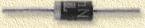
1N4004 Diode |
Scematics and assembly
Below you will find a scematics drawing of the homebrew
BasicStamp;
Homebrew BasicStamp scematics
Use this drawing to guide you through assembling the
homebrew BasicStamp.
Tip: Usually I print out such a scematic and put it
into a transparant sleeve. Then for each connection I make on the breadboard,
I draw a line on the transparant sleeve over the connections I just
made. This way you can keep track of which connections you completed
and which
ones still have to be done.
Some notes here:
| 1. |
The S1 switch (and the blue colored lines) are optional. S1 is
used to reset the PIC if needed. So you can use a simple contact
bridge aswell, which you simply shortcut when you want a reset. Or:
you simply unplug the power supply, which results in the same effect. |
| 2. |
Pins 7 and 10 of the MAX232 ic are NOT connected. |
| 3. |
C1, C2, C3 and C4 are polarity sensitive! |
| 4. |
The PIC16C57 is the Parallax PBasic interpreter, the largest chip
of them all. |
| 5. |
The 24LC16B is the EEPROM, the smallest chip of them all. |
| 6. |
The  -symbol
indicates GROUND, which in this case is the same as the MINUS of
the powersupply. -symbol
indicates GROUND, which in this case is the same as the MINUS of
the powersupply. |
| 7. |
The PC Serialport connector is usually a so called
DB-9 (also Sub-9) or DB-25 (known as Sub-25) connector. This port
is being used to
program the BasicStamp ones it's operational. |
| 8. |
Before connecting the powersupply VERIFY the +5V and the GND! |
Verifying you homebrew
Using a so called multi-meter or volt-meter (you don't
need a high-tech one, just a simple one will do), we can verify if (most
of it) is connected properly.
In the drawing below,
you
will
see
red
balloons indicating the power that should be measured on these point.
This drawing shows only that part of the design that is relevant for
the measuring points;
Measuring points
|
